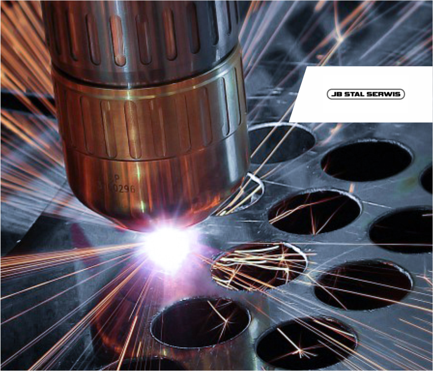
Eksperci w produkcji maszyn CNC do cięcia plazmowego i gazowego
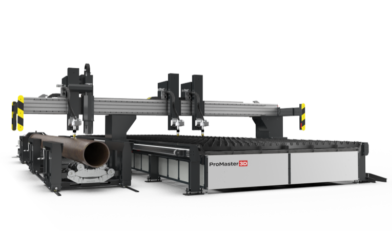
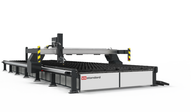
Dostarczamy rozwiązania dla wymagających klientów wszędzie tam gdzie potrzebne jest cięcie plazmowe i gazowe z jednoczesnym fazowaniem i znakowaniem detali.
Naszym priorytetem jest maksymalne wykorzystanie potencjału technologii cięcia plazmowego i gazowego. Połączenie tych zaawansowanych technologii z dodatkowymi funkcjonalnościami naszych maszyn daje niezrównane możliwości wielozadaniowości. Dzięki temu, nasze maszyny oferują nie tylko wszechstronność, ale także niezwykle szeroki zakres działania, który wyróżnia je spośród innych technologii.


Każdego dnia rozmawiamy z naszymi partnerami i obserwujemy rozwój przemysłu i potrzeb związanych z cięciem stali i aluminium. Wymagania jakościowe oraz potrzeby klientów stale wzrastają dlatego przez 17 lat rozwijamy funkcjonalności i bezpieczeństwo naszych maszyn. Nieoceniony jest też czas, a więc skupiamy się przede wszystkim na tym aby wdrażane przez nas rozwiązania rzeczywiście optymalizowały procesy produkcyjne i pozwalały na zwiększenie możliwości parków maszynowych firm produkcyjnych w Polsce.